|
|
Design flow of ERBS |
| |
① Determine beam shape
|
| |
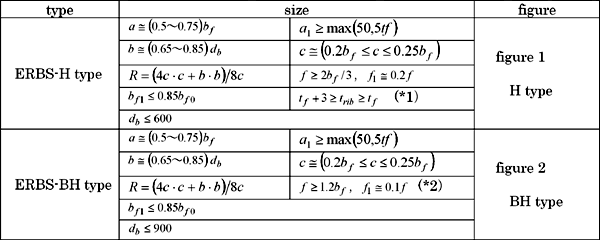
ERBS shape and size is determined using Table 1~2 and Figure 1~3, by applying experimental and
analytical results and FEMA-350(Reference 1).
|
|
Table 1 Shape and Size of the Beam |
 |
| (Reference 1) |
“FEMA-350, Recommended Seismic Design Criteria for New Steel Moment-Frame
Buildings, June, 2000” |
| |
(*1)Align the beam flange bottom and horizontal beam end wing, when tribtriband using the back up bar.
(*2)Set the joint at the end of f. or on the inner side toward the the beam center
(*3)Boxing in the H-type inner wing is not always required.
|
|
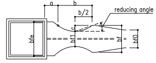
| Definition of terms |
| Reduced section:reduced bottom section where beam flange width is bf1 |
| db:beam depth |
bf 0: center flange width |
bf:inner flange width |
| c:depth of flange reduction |
bf1:reduced flange width |
bfe:flange width at face |
| α:point at flange width is bf |
a:length between face and α |
b:length of reduction |
| f : length of the inner wing |
f1: parallel part length of the inner wing |
r :radius of reduction |
| t f :flange thickness |
Zp:plastic section modulus at reduced section(including web) |
| Mf :end beam moment |
Zb :plastic section modulus at beam end,Zb=t f ・bfe・(db-t f ) |
| Af1:flange cross sectional area at reduced section,Af1=bf1 ・t f |
| e:space size at beam flange side |
|
| |
Table 2 Prequalification Data for ERBS Connections |
Parameters & Details |
Limitations |
Beam symmetry |
FWing and reduction shape should be symmetric |
Width-thickness ratio of beam |
FA rank. Evaluate it using the center flange width bf 0, even with the reduced section. |
Lateral stiffening of the beam |
“Lateral stiffening ensuring horizontal load carrying capacity”.
Evaluate using A f 1and i y , at the reduction length. Gusset plates of stiffening member should not
be welded, within the range a+b from the beam end. |
Minimum
span- to-depth ratio |
[span/depth] ≥ 5 |
Centre flange width |
Centre flange width:bf 0 ≤ 300 |
Flange thickness t f |
40mm maximum |
Eccentric connection to column |
Flange width at face bf e is within the column width. |
Floor rigidity |
Concrete slab or metal deck and concrete or horizontal bracing should be used. |
elded studs
of composite slab |
Welded studs should not be placed in the area of the beam flange between the column face and 6 inches beyond the extreme end of the ERBS(a+b+15cm). |
Supplementary information about the shape |
・Point α provides length a and b.
・When flange width of the face is increased by more than bf , extend it nearly in the tangential direction from the point α. Flange width at face bf e is more than bf.
・Beam end size related to the ultrasonic inspection and welding is shown in Figure 3. |
|
| |
|
Figure 1 ERBS-H shape and size |
| |
|
Figure 2 ERBS-BH shape and size |
| |
|
Figure3 Beam end size for various methods |
| |
| The beam shape design flow of H and BH-types is shown in figure 4. |
|
Figure 4 Beam shape design flow |
| |
(Note 1) Initial value of the hinge location referenced according to experiment is shown below.

(Note 2) Adjust the flange reducing angle,
estimated using analysis and experiment.
b/2c ≒ 2.9 |
 |
|
② Frame analysis
|
| |
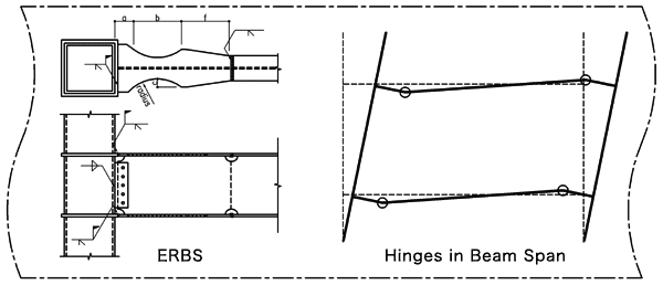
Frame analysis should be conducted according to the models which accurately
expressing beam reduction shape characteristics. However, it should be
implemented using the following frame analysis method having a rigid zone,
when the one described above is not used.
・Model the reduced section and rigid zone using the frame analysis program.
・Set the rigid zone length a + b / 2 from the column face. Set the reduced
section length b/2.
・Set the joint location a + b from the column face, dividing it into the
reduced section and center section.
・The beam stiffness does not consider the composite action with concrete
slab.
|
|
|
Figure 5 Frame analysis with rigid zone |
| |
③ Check stress on frame structure
|
| |
・The allowable unit stress of buckling of the bending member shall be evaluated using bf 1 and t f in the reduced section.
The interval between the support points of the compression flange lb must be the length between the column face (or column center) and the first support point from the column face, where the reduced section is located.
・Set the location for the design of the section at the rigid zone end.
・The allowable unit stress of buckling of the compression member of the
beams shall be evaluated using the radius of gyration of the reduced section,where the reduced section is located.
|
|
④ Check stress concentration of the loor slab
|
| |
Welded studs should not be placed in the area of the beam flange areabetween the column face and 6 inches beyond the extreme end of the ERBS( a + b + 15cm). The shearing force transfer of the floor slab should bedesigned taking into account the fewer studs effect,
where an extra shearforce occurs at the brace. The allowable strength of studs meets the requirementof AIJ, 1985, Design Recommendations for Composite Constructions, etc
|
|
⑤ Check the RBS section
|
| |
Verify that the bending and shear strength satisfy the RBS design procedure.
The beam end connection bears the moment of the flange and the shear force of the web.
|
|
ⅰ)Design for the beam end moment |
| ・Evaluation of the bending strength of connections |
| |
Bending moment working at the end connection of the beam is calculated as follows.
In this procedure, the beam end moment M f is determined using the load condition and mechanism as shown in figure
6~7. When the permanent load condition is different, the corresponding
shearing force Vp should be calculated.
|
|
| |
M f = Mpr+Vpx = Cpr Ry Zp Fy+Vpx (1)
Mpr = Cpr Ry Zp Fy (2)
M f :the moment demands at the column face
Mpr :the probable peak plastic hinge moment
Cpr:the peak connection strength coefficient, including strain hardening, local restraint, additional reinforcement, and other connection conditions. Cpr=1.15 for RBS.
Ry:A coefficient, applicable to the beam or girder material, Ry=1.1
Zp:effective plastic modulus of the section at the location of the plastic hinge (including the web).
Fy:the specified design strength
Vp:the shear force at the plastic hinge.
Vp = |
Mpr+Mpr+PL’/2+wL’2/2 |
|
| |
L’ |
x :the length between the plastic hinge and column face, x=a+b/2
p:the concentrated load on the beam center
w:the distributed load on the beam.
|
|
|
Figure 6 Sample calculation of shear at a plastic hinge taking into account the gravity loads
|
|
Figure 7 Calculation of demands at a column face
|
| ・Check the bending strength of the connection |
| |
If the following equation is satisfied, the design is acceptable
M f < Ry Zb Fy (4)
Zb:plastic section modulus at the beam end. Zb = tf ・bfe ・(db-t f )
|
|
| ⅱ) Design for the shear of the connection |
| |
Calculate the shear at the column face Vf according to the equation
τ = Vf /tw(db-2t f-2Sr )
τ/fs ≦ 1.0
where,
QⅬ: shear due to permanent load.
fs : allowable shear stress under temporary forces
Sr: height of weld access hole
For the rest, panel zone and continuity plates should be calculated accordingto “Design Standard for Steel Structures”, “AIJ, 2001, Recommendation forDesign of Connections in Steel Structures,” etc.
|
|
⑥ Check the interstory drift angle
|
| |
When the interstory drift angle is evaluated using the “frame analysismethod with rigid zone” in frame analysis, the calculated displacementis smaller than the actual one with respect to the less flexural lengthof the beam. Therefore, it should be checked minutely by following thesimple calculation of safety side estimation. (In order to calculate thedisplacement accurately, it should be evaluated using another non-uniformbeam section model, etc. The calculated result of frame displacement witha non-uniform beam section element is shown in reference A.)
・Model the beam using the uniform section element. The section is the centerof the steel beam section. The beam stiffness does not take into accountthe composite action with concrete slab in the same way as the frame analysis.
・Check that the interstory drift angle is within the allowable range ofthe calculated displacement.
This frame displacement having a uniform section element provides safety estimation, because the displacement is greater than that of the actual accurate RBS section analysis. The beam deflection caused by permanent loads is safety, because the displacement is greater than the actual one.
|
|
⑦ Prevent the damage of the brace end and section connection
|
Check the “connection to ensure the horizontal load carrying capacity” at the beam end as follows.
・The moment demands of the connection
| |
The bending moment acting at the beam end of the horizontal load-carryingcapacity is the moment demanded at the column face M f
Check that the connection does not break by multiplying safety factorwith the moment. While calculating this moment M fpermanent load and Cpris considered as a supplementary factor.
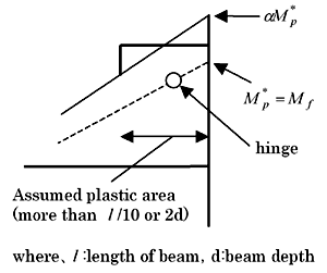
The design bending moment of connection αM*p is given by the following expression
αM*p = αMf = (Cpr Ry Zp Fy+Vpx)
|
 |
|
・Check the ultimate bending moment of the connection
| |
Check that the connection does not breake, assuming that the moment demandsof connection is αM*p However, it is always satisfied using the following calculation, becausethe RBS section check is executed using the allowable stress
Multiplying the safety factor α with the RBS equation,
α(Ry Zb Fy) > αM f = αM*p
(400 N quality carbon steel:α = 1.3)
ZbσU = 400 Zb > α(Ry Zb Fy)=1.3×1.1 Zb×235=336 Zb > αM*p OK
(490 N quality carbon steel:α = 1.2)
ZbσU = 490 Zb > α(Ry Zb Fy) =1.2×1.1 Zb×345=455 Zb > αM*p OK
|
|
⑧ Prevent local buckling, etc
|
To prevent lateral buckling, the procedure for checking the beam is asfollows:
・Apply the case “secure the lateral stiffening supports at equal distancealong the full length of the beam”
| |
The lateral stiffening supports the distance at the beam end within therange for l/ne The lateral stiffening supports number ne with a slenderness ratio along the minor axis of the reduced beam section λye by satisfying the following equation.
λye ≦ 170+20 ne (400 N quality carbon steel)
λye ≦ 130+20 ne (490 N quality carbon steel)
The lateral stiffening interval at the center of the beam is within therange for l/nc nc is the lateral stiffening number with a slenderness ratio along the minoraxis of the beam center section λyc by satisfying the following equation.
λyc ≦ 170+20 nc (400 N quality carbon steel)
λyc ≦ 130+20 nc(490 N quality carbon steel)
.wherel :beam length
λye:slenderness ratio along the minor axis of the reduced beam section( = l/iye)
λyc:slenderness ratio along the minor axis of the beam center section( = l/iyc)
iye:radius of gyration along the minor axis of the reduced beam section,√(I y1/A1 )
iyc:radius of gyration along the minor axis of the beam center section,√(I y/A)
I y1,I y:moment of inertia of the reduced beam section and beam center sectionalong the minor axis.
A1,A:area of the reduced beam section and the beam center section.
|
|
・Applying the case “secure the lateral stiffening member mainly near thebeam beam” |
| |
Secure the lateral stiffening supports at the distance calculated usingthe following equation in the area where the bending moment exceeds theyield moment. The moment distribution used to calculate the lateral stiffeningsupports is also estimated, assuming that the moment at the column faceis Mf . Furthermore, the yield moment should be calculated using the reducedbeam section at the end and the beam center section at the center of thebeam.
Multiply the safety factor α with the moment distribution for calculatingthe lateral stiffening supports. The safety factor α is 1.2 for 400 N qualitycarbon steel, and 1.1 for 490 N quality carbon steel.
For 400 N quality carbon steel,
| the distance between the supports at the end: |
|
≦ 250 and |
|
|
|
|
Af1 |
iye |
| the distance between the supports at the center: |
|
≦ 250 and |
|
|
|
|
Af 0 |
iyc |
For 490 N quality carbon steel,
| the distance between the supports at the end: |
|
≦ 200 and |
|
|
|
|
Af1 |
iye |
| the distance between the supports at the center: |
|
≦ 200 and |
|
≦ 50 |
|
|
Af 0 |
iyc |
Af1:flange cross-sectional area at reduced section , Af1 = bf1・t f
Af 0:flange cross-sectional area at the center , Af0 = bf 0・t f
lbe:the distance between the supports at the reduced beam section
lbc:the distance between the supports at the center
|
|
⑨ Check the horizontal load-carrying capacity
|
| |
Assume that the plastic hinges of the beam develop at the reduced beamsection,while calculating the horizontal load carrying capacity.Cprnot multiplied while calculatiing the horizontal load-carrying capacity.
If it is calculated using the frame analysis program, it can be executedusing the same rigid zone model employing the frame analysis method ofthe 1st step design.
|
|

