 Top
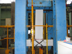
Top| Test bed |
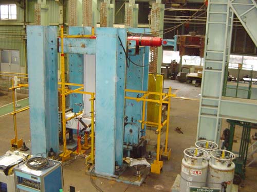 |
| (by JFE Techno-Research Corporation) |
| Specimens |
 |
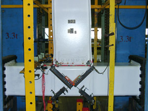
ERBS-H specimen |
 |
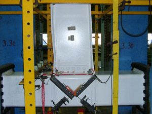
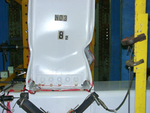
ERBS-BH specimen |
|
||||||||||||||||||||||||||||||||||||||||||||||||||||||||||||||||||||||||||
| Tensile test of material | ||||||||||||||||||||||||||||||||||||||||||||||||||||||||||||||||||||||||||
|
||||||||||||||||||||||||||||||||||||||||||||||||||||||||||||||||||||||||||
Loading history |
||||||||||||||||||
 |
||||||||||||||||||
Cyclic behavior of the ERBS-H connection |
||||||||||||||||||
 |
||||||||||||||||||
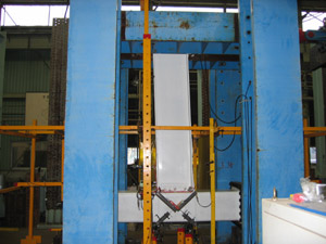
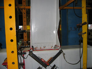
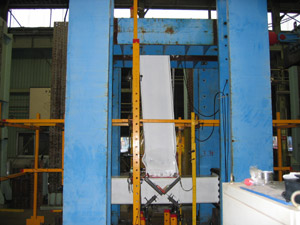
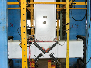
Photographs of ERBS-H specimen |
||||||||||||||||||
|
||||||||||||||||||
Cyclic behavior of the ERBS-BH connection |
||||||||||||||||||
 |
||||||||||||||||||
Photographs of ERBS-BH specimen |
||||||||||||||||||
|
| Strain distribution of outer beam flange |
 |
ERBS-H tensile strain on top flange |
 |
ERBS-H compressive strain on bottom flange |
 |
ERBS-BH tensile strain on top flange |
 |
ERBS-BH compressive strain on bottom flange |